1 Introduction
Before we start creating databases with SQL, we need to ask ourselves what the database should look like in the end. Which tables and columns are needed and how should they be connected? Such considerations about the structures can be visualized with an Entity Relationship Diagram.
And that’s what this post is all about.
To draw ER diagrams I used Drawio. If you need an overview sheet for the notation forms shown later, you can download it from my GitHub Account.
2 What is a Entity Relationship Diagram?
Entity Relationship Diagrams (ERD) or Entity Relationship Models (ERM) represent the data in any system. ERDs are mostly used to show in detail how data is stored in relational databases. Entity Relationship Diagrams do not necessarily show how data is manipulated or the exact process it goes through, but how data entities are structured and related to each other.
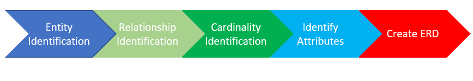
3 Main components of ERDs
There are three main components in ERDs:
- Entity
- Attributes
- Relationships
3.1 Entity
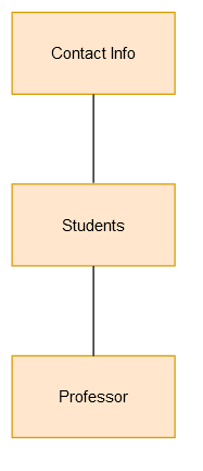
A individually identifiable object of reality such as a person, concept or event for which there may be stored data. The entity is typically represented as a rectangle.
3.2 Attributes
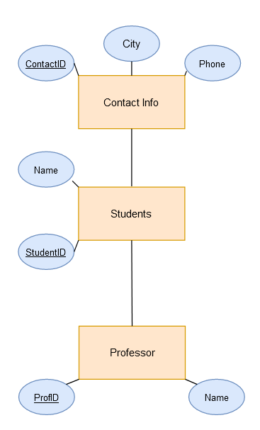
The attributes specify what is of interest about an entity (in context). They are usually drawn as ellipses floating around the entity.
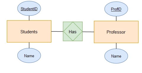
3.3 Relationships
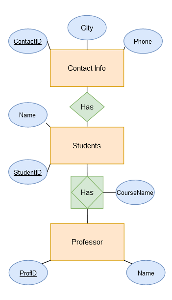
The relationship indicates how entities affect or are connected to each other. It is usually represented as a diamond.
4 Special circumstances
4.1 Strong Entity
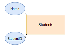
The identification of an entity is possible by one or more values of attributes of the same entity type.
For example, the StudentID is identifying for the Students entity type.
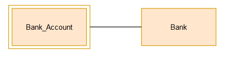
4.2 Weak Entity
To identify such an entity, an attribute value of another entity of strong type related to the weak entity is required. The weak entity is represented by a double rectangle.
For example - a bank account cannot be uniquely identified without knowing the bank to which the account belongs, so the bank account is a weak entity.
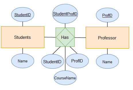
4.3 Associative entity
Associative entities are connections that describe a relationship between two different entities. These entities can have many-to-many relationships, which means that one of the associative entities can have multiple relationships and connections to a parent or child entity.
Associative entities convey information about their attributes and their connections. They are considered as entity because they have attributes and they are considered as relationship because they connect entities. These types of entities very often have many relationships and connections because they are relatable, but they can have independent meaning from other entities. In a relational model, it is also common for the associative entity to have at least one attribute that is distinct from the identifier entity. Associative entities can also be participants in relationships that are separate from the relationships of the associated entities.
Primary keys should also be a part of associative entities because they are identifiers that join specific tables in a relational model. Although tables may contain only one, primary keys are combinations of columns that uniquely specify rows. One difference between unique keys and primary keys is that primary keys can enforce a “non-null” constraint on a table or entity. Another aspect that distinguishes primary keys from unique keys is that primary keys are selected as keys of greatest or first importance. Primary indexes are created for primary key management and for ease of use and enforcement by a database manager.
Associative entities are contained in and used by junction tables - tables in a relational model that contain common fields from two or more other tables. Junction tables are used because they can handle many-to-many relationships in a given database. An example of a database that employs the associative entity through the use of a junction table is student enrollment in a course. In this case, a table containing data about students is indirectly linked to a table containing data about courses through an intermediate table that contains data associated with student and course data from the join tables.
Source: EasyTechJunkie
Associative entities are usually represented as a diamond with a surrounding rectangle.
To be quite precise, you can also add the attributes here.
5 Cardinality
Cardinality specifies at the relationship type level for each of the entity types involved how many concrete relationships of that type its entities can or must be involved in. Different notations can be used to define the cardinality.
Notation forms in ER diagrams:
- Chen-Notation
- Modified Chen Notation (MC-Notation)
- Min-Max-Notation
- Martin-Notation (Crow’s foot notation)
5.1 Chen-Notation
To represent the cardinalities of binary relation types, the digit 1, in the sense of 0 or 1, and the letters n and m, in the sense of 0 to infinity, are used.
1:1 ([0 or 1] to [1 or 0])
Any entity from the first entity set can be related to at most one entity from the second entity set and vice versa.
1:n ([0 or 1] to any number)
Any entity from the first entity set can be related to any number of entities from the second entity set. Each entity from the second entity set can be related to at most one entity from the first entity set.
n:m (any number to any number)
Any entity from the first entity set can be related to any number of entities from the second entity set and vice versa.
Source: Wikiwand
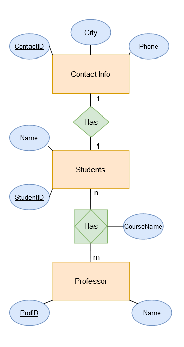
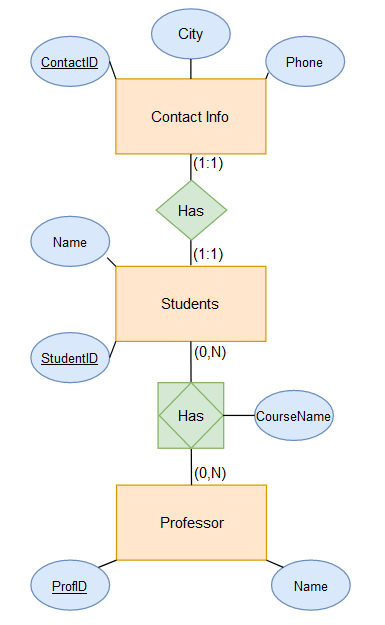
As we can see from the diagram, a student has exactly one contact information associated with him. This is a 1:1 relationship.
If we look at the relationship between students and professors, we see that several students can have one professor, but also vice versa, one professor can have several students.
5.2 Modified Chen Notation (MC-Notation)
Modified Chen Notation (MC Notation) is an extension of Chen Notation in which the statement “no or one element” is indicated by the letter c (choice, can), and the statement “one or more element(s)” is indicated by the letter m (must, multiple).
1:1 (1 to 1)
Each entity of the first entity set is related to exactly one entity of the second entity set, and vice versa.
1:c (1 to [0 or 1])
Each entity of the first entity set can be related to at most one entity of the second entity set. Each entity of the second entity set is related to exactly one entity of the first entity set.
1:m (1 to [at least 1])
Each entity of the first entity set is related to at least one entity of the second entity set. Each entity of the second entity set is related to exactly one entity of the first entity set.
1:mc (1 to [any number])
Each entity of the first entity set can be related to any number of entities of the second entity set. Each entity of the second entity set is related to exactly one entity of the first entity set.
c:c ([0 or 1] to [0 or 1]) Equivalent to 1:1 in Chen notation
Each entity of the first entity set can be related to at most one entity of the second entity set, and vice versa.
c:m ([0 or 1] to [at least 1])
Each entity of the first entity set is related to at least one entity of the second entity set. Each entity of the second entity set can be related to at most one entity of the first entity set.
c:mc ([0 or 1] to [any number]) Equivalent to 1:n in Chen notation
Each entity of the first entity set can be related to any number of entities of the second entity set. Each entity of the second entity set can be related to at most one entity of the first entity set.
m:m ([at least 1] to [at least 1])
Each entity of the first entity set is related to at least one entity of the second entity set, and vice versa.
m:mc ([at least 1] to [any number])
Each entity of the first entity set can be related to any number of entities of the second entity set. Each entity of the second entity set is related to at least one entity of the first entity set.
mc:mc ([any number] to [any number]) Equivalent to m:n in Chen notation
Any entity of the first entity set can be related to any number of entities of the second entity set, and vice versa.
Source: Wikiwand
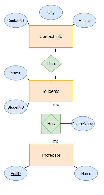
Using the modified Chen notation, we can now see that it is mandatory for each registered student to have their contact information stored (1:1 connection). If he cannot do this, he cannot register at the university.
5.3 Min-Max-Notation
Min-Max notation is a way of constraining the cardinality of a relationship between entity types in an entity-relationship model. It was introduced because Chen notation allows only restricted statements about a relationship. With the (min,max) notation, both lower and upper bounds can be expressed precisely.
In Min-Max notation, an ordered pair with a minimum and a maximum value is specified for each entity type involved in a relationship. These values indicate the minimum number of relationship expressions in which the entity expressions must participate and the maximum number in which they may participate.
Source: Wikiwand
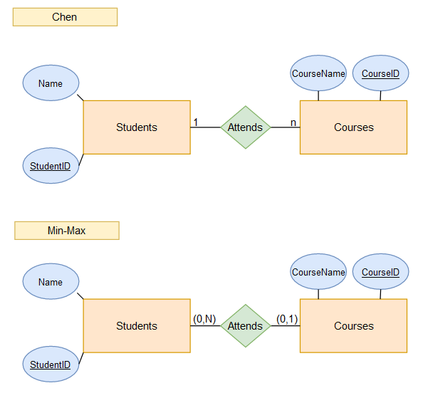
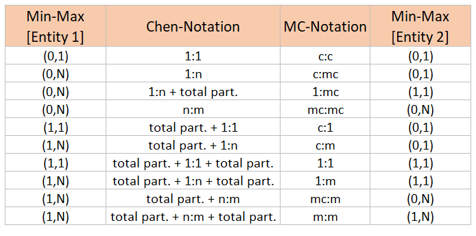
Here is a comparison of the Min-Max notation with the Chen notation:
How to read the Chen and Min-Max-Notation:
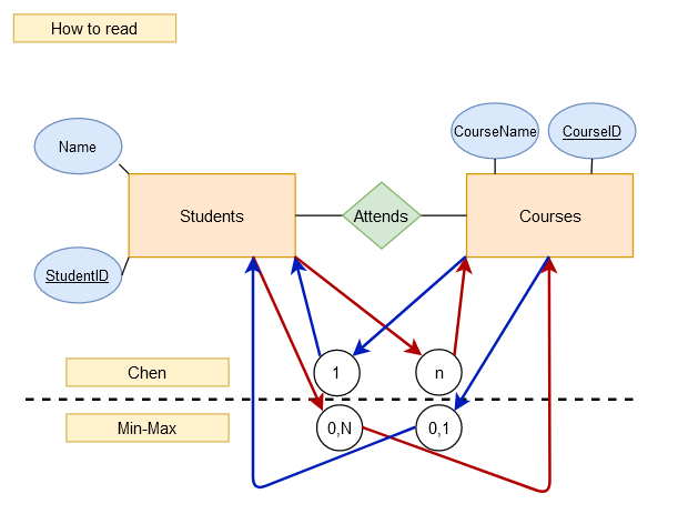
If you follow the red arrows, you will see that each student can enroll in n courses. No course can be taken twice by a student (blue arrows).
The Min-Max notation is written exactly the other way around than the Chen notation (which still includes additional lower and upper bounds as information).
This is how to express this relationship with MC notation:
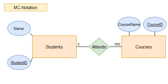
Comparison of Min-Max Notation, Chen Notation and MC Notation:
Source: Wikiwand
This applied to our example would result in the following diagram:
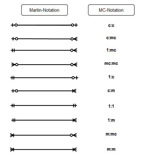
5.4 Martin-Notation (Crow’s foot notation)
The Martin notation (also called crow’s foot notation) is a notation form to represent simplified entity-relationship models. Her naming comes from the fact that she uses so-called crow’s feet for a 1:n relationship.
Here again is an overview comparing Martin notation with MC notation:
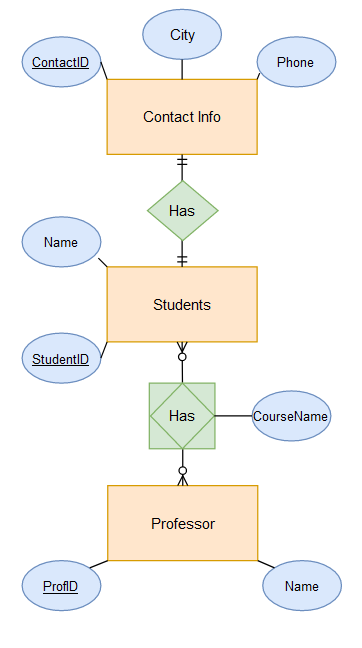
This applied to our example would result in the following diagram:
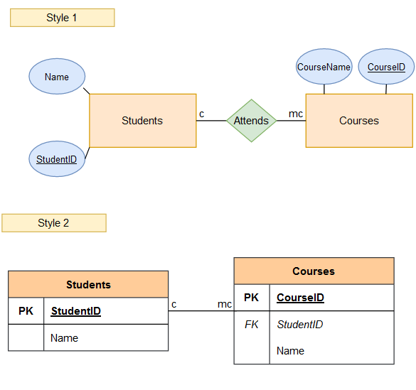
6 Different styles of displaying ER diagrams
ER Diagrams can be displayed in different ways. Here I have compared two of the most common variants.
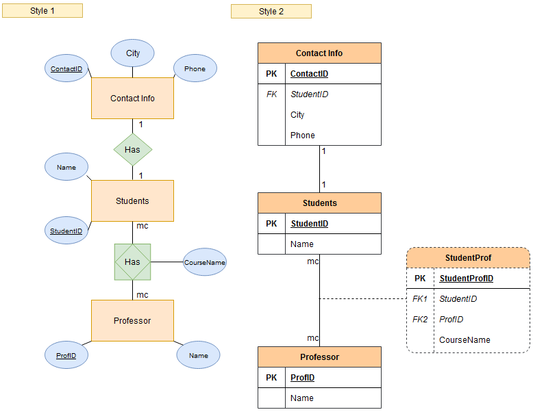
Note: For a 1:1 connection as is the case with Stundets-Contact Info, for example, I only need a Foreign Key for one of the two tables.
Note: If there is a 1:n connection, then the foreign key is usually written to the table of n.
7 Best Practice for Developing Effective ER Diagrams
- Eliminate any redundant entities or relationships
- Make sure all entities and relationships are labeled correctly
- Make sure the ER diagram supports all the data you need to store
- Make sure that each entity appears only once in the ER diagram
- All relationships, entities and attributes to be represented in the diagram must be named
- Relationships with each other should never be connected
- Important parts of the ER diagram should be highlighted with colors
8 Conclusion
In this post, I introduced what ER diagrams are and what they consist of. Furthermore, I explained different notation forms and how to use them. Finally, I showed two different variants of how to display ER diagrams.